
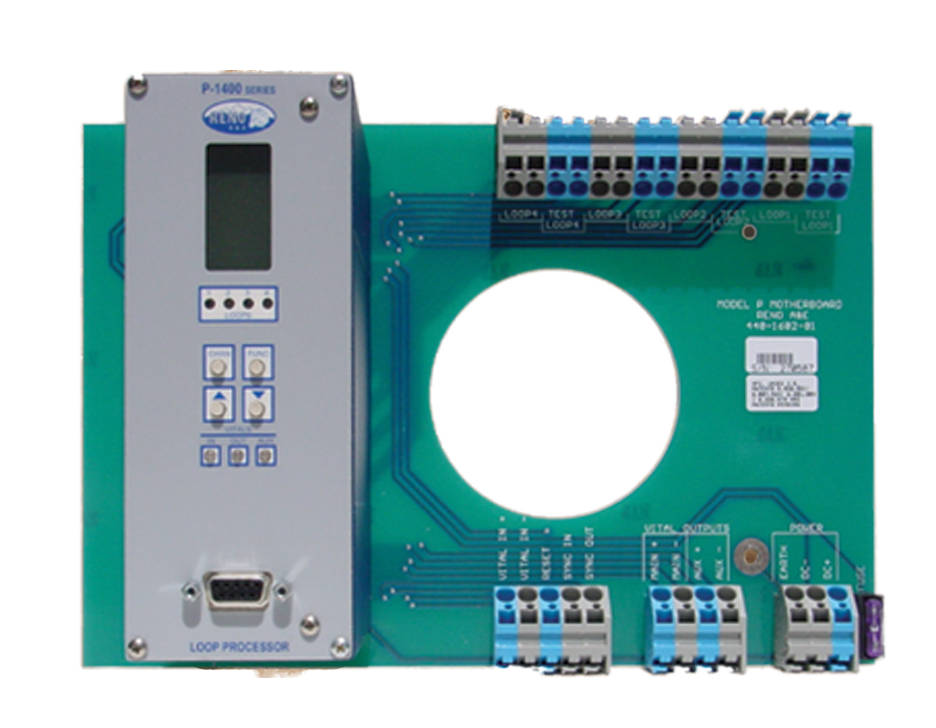
Meet Riotech’s P-1400
The Model P-1400 is an inductive loop processor developed to provide detection of railway equipment.
Key Features
Monitors and analyzes signals from 4 inductive loops with independent check loops
Generates occupied/unoccupied signals for each loop
Isolated vital input for incorporating various logic elements
Periodically activates check loops to stimulate rail equipment presence
Displays failure message if inductance change during check cycle doesn’t match a stored reference value
Capable of providing occupancy detection in challenging conditions where conventional track circuits fail
Unaffected by low ballast, rusty rail or section of track with salt
Easy operation with default parameters for quick setup
Programming via front pannel or serial port
Software available for programming
Technical Specifications
Overview: The Model P-1400 is an inductive loop processor developed to provide detection of railway equipment in small and large detection areas typicallyrequired for yard switch, interlocking, and moveable bridge occupancy detection. Switch protection can be configured to prevent side-swipe movements typically encountered in classification yards and certain flat switching operations. The P-1400 processor is designed to directly replace older technology processors that mount in ground level enclosures. Current state of the art, digital loop processing technology, combined with railroad standard vital monitoring techniques and a unique self-check function provide consistent and reliable detection. In addition, expanded user selectable features provide flexibility in set-up, operation, and performance of the processor.
Function: The Model P-1400 is an inductive loop processor that monitors and analyzes signals from four inductive loops each equipped with an independent check loop. An occupied / unoccupied signal as well as health status is generated for each loop for internal processing. In addition, an isolated vital input is provided to permit the inclusion of various logic elements within the internal processing equations. The internal loop occupancy bits and the auxiliary input can be logically combined and mapped to control two vital outputs; one main vital output and one auxiliary vital output. The main and the auxiliary vital outputs can be controlled by any combination of the four loops and/or the vital input. A loop failure will deactivate either vital output that the loop status input and/or loop health status input is programmed to control. The check loop circuits are programmed to periodically simulate rail equipment within the loop detection areas as a means of verifying loop integrity. The vital outputs utilize AC coupled drive circuitry and the vital inputs are continuously monitored and tested to validate they are in the correct state.
The P-1400 Difference: High-speed digital processing continuously monitors and updates the detection parameters of four independent loop circuits. The P-1400 will not “de-tune” or lose sensitivity and can maintain the presence of rail equipment as long as it remains in the loop detection zone. This “infinite presence” mode of operation assures long term detection zone.
Loop Inputs: The four loops provide consistent and reliable detection throughout the long detection zone required for switch and side-swipe protection. Older technology processors were subject to several problems because they could only monitor a single long loop. The distance traveled into a single long loop before detection occurs varies greatly depending on the type of rail equipment. Detection of the equipment can also be dropped prior to the vehicle clearing the loop. The detection drop point can vary greatly depending on the size of the equipment. This effect is amplified when equipment is present within the detection zone for extended periods of time. By utilizing four loops, the effects of environmental tracking are minimized to retain predictable detection and dropout points when equipment enters or exits the detection zone. The four loop configuration is more stable than a single long loop and is also less likely to respond to rail movement or the making and breaking of rail joints.
Loop Input Configuration: There are numerous specialty applications for railroad signal loop processors. These applications are often dependent upon the original engineering and design of the signal system. The P-1400 has the capability to provide occupancy detection where conventional track circuits cannot. Conditions such as low ballast, rusty rail, or sections of track where salt is present have no effect of the operation of the Model P-1400.
Required Loop Inputs: The Model P-1400 is designed to be used with virtually any size loop, but best results will occur if it is applied in accordance with recommended minimum size and area configurations. Because the height of the detection field is a function of loop size and surrounding conductivity, proper loop geometry must be applied in order to assure detection of all classes of rail cars. Consideration must also be given to the number of wire turns in the loop versus the inductance of the lead-in cable between the loop and the Model P-1400. This assures adequate sensitivity in order to detect and hold all types of rail equipment. The test loop consists of a single turn of wire that runs the entire perimeter of the detection loop. It can either be contained within an integrated loop cable or applied as a separate conductor external to the detection loop. One of the most critical areas with any type of loop is the use of proper wire insulation and connection techniques. Wire manufactured with cross-linked polyethylene insulation is the only insulation approved for use due to its ability to eliminate water absorption thereby minimizing the effects of variable capacitance based on environmental changes.
Self-Check: The Model P-1400 periodically activates each check loop simulating the presence of rail equipment within the detection loop. If the inductance change generated during the check cycle of any loop does not match a stored reference value, the processor displays a message indicating a failure of that particular loop.
Loop Scanning: The Model P-1400 utilizes a sequential scanning technique to eliminate pickup from adjacent loops. This method allows the Model P-1400 to independently turn each loop oscillator on and off on a sequential basis. In this manner, only one loop is active at a time. The scanning period is approximately 10 milliseconds per loop resulting in the appearance of all loops being active simultaneously. By scanning each loop, any interference generated by an adjacent loop is totally eliminated assuring no erratic operation from cross-talk.
Input / Output Mapping: Input/output mapping allows the user to assign the inputs (loop, vital, and/or health) to the vital outputs. Various combinations of the loop inputs can be assigned to control the vital outputs, effectively providing multiple output functions from the same loop inputs. A vital output of one P-1400 can be connected to a vital input of another P-1400, allowing two processors to share monitoring duties of the same loops. This application is commonly used in yard application where side-swipe protection is required to prevent a turnout from reversing until a rail car reaches the clearance point beyond the frog of the switch.
Programming: Operation of the Model P-1400 is extremely simple. Default parameters assure that loops are up and running without the need for extensive or specialized test equipment. All programming elements can be addressed either through the front panel of the Model P-1400 or via a serial port to a personal computer. Software to access the serial port for programming is available upon request with each Model U-1400.